


A friend reached out hoping I could 3D model a rare knife/machete he had. I am always happy to help, so I did what I could. It generally went very well however the blade edges were difficult due to the inconsistent depth relative to the true edge, following curves that were difficult to precisely define.
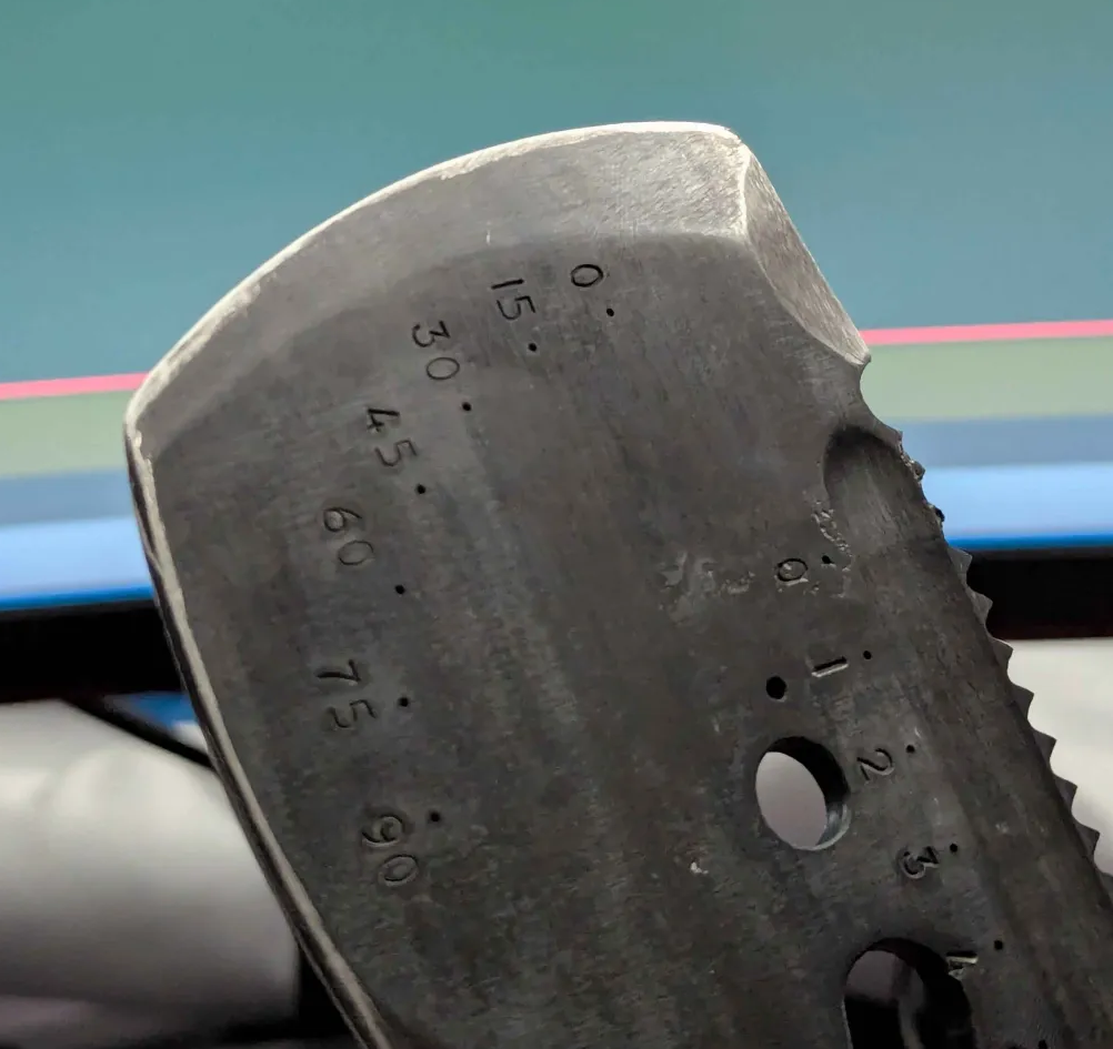
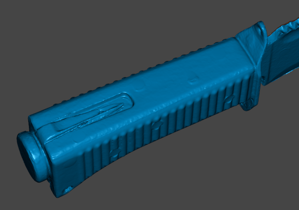
For this, I wanted to throw a few different tools/techniques at the problem to see what would aid me most. I began with my new budget 3d scanner, which while fun, doesn’t magically generate true CAD files. It can create a reference mesh with some limitations on things like blade edges and world alignment, but is still a good effort to proceed with.

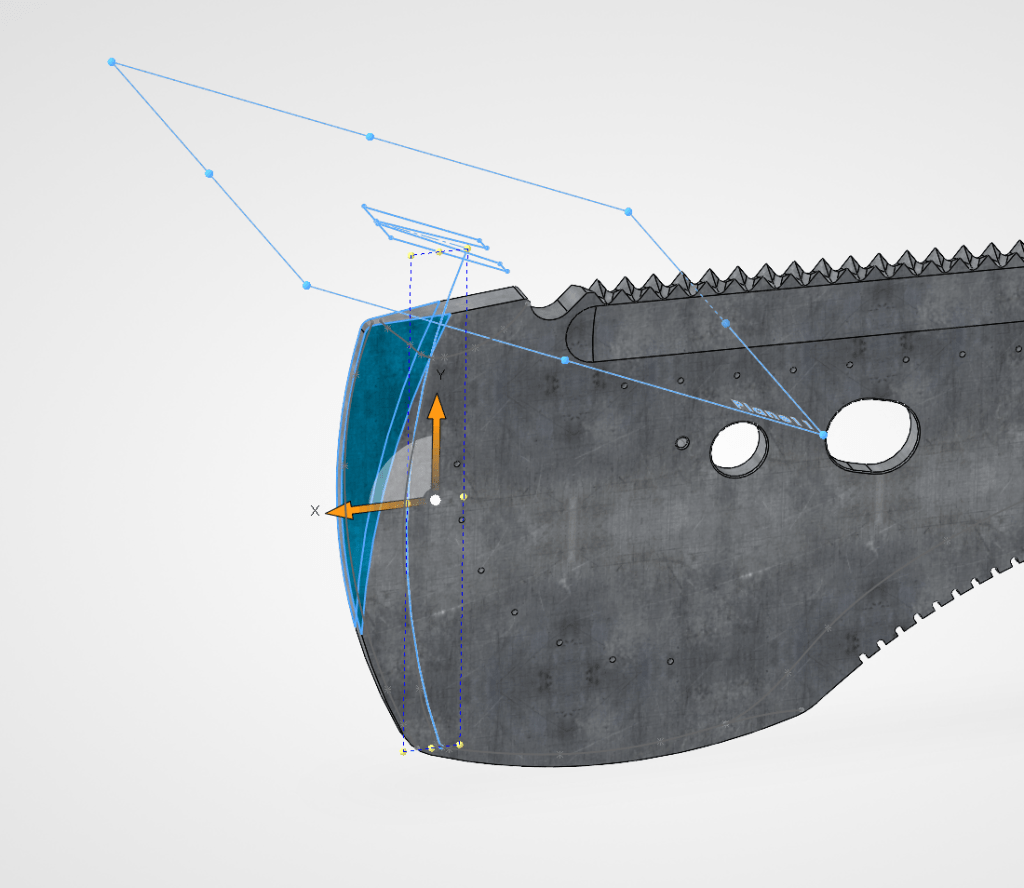
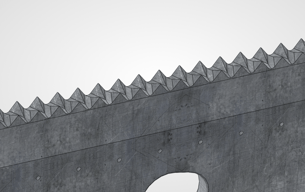
Following that I used a 180mm diameter telecentric lens on my DIY stitching gantry to compose a dimensionally accurate perspective-less photo of the subject. With the stitched image, I was able to use Adobe Photoshop and Illustrator to create outlines, curve paths, and sketch reference geometry.

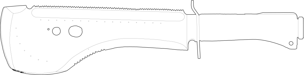
Taking these into SolidWorks I began the modeling process. I was hesitant to split apart the friction welded(?) bakelite grip to investigate the internals, so I left those partially unmodeled. As my friends intention was to create only a single replica using more modern grip materials such as G10 laminate, the internals would be obsoleted anyways.

All in all, I am happy with the results! There were some tricky modeling challenges, but each challenge is an opportunity to learn and hone your skills.


The drawing package, as is typical, took 3-4 times as long as the modeling. One must consider the manufacturing methods at play, the theoretical preferences of the viewer based on their experience level, and balance readability vs detail. Every possible measurement for each component must be explicitly called out, or easily inferred.
As someone who has gone from blueprint to 3D Cad many times before, I understand the challenges it brings, and aim to provide the best reference material possible.

Leave a Reply